3D Camera and Objects
Throughout my past examples, I’ve only used the 2D camera, so now let’s explore Bevy’s 3D world.
Spawning a 3D Camera
Let’s start by creating a new project with a 3D camera.
use bevy::prelude::*;

fn main() {
    App::new()
        .add_plugins(DefaultPlugins)
        .add_systems(Startup, setup)
        .run();
}

fn setup(
    mut commands: Commands,
) {
    // camera
        commands.spawn((
        Camera3d::default(),
        Transform::from_xyz(5.0, 5.0, 5.0).looking_at(Vec3::ZERO, Vec3::Y),
    ));
}
We spawn the camera as always, except this time it’s Camera3d. Then, we set its position somewhere toward the top corner and decide what it will be facing.
Another cool thing I found is the looking_at() function. It essentially tells the camera where to look, taking in two arguments. The first argument is a vector representing the target position — this is where the camera will face. The second argument is the up direction, which helps define the correct rotation of the camera. If we use Vec3::Y, the camera stays upright. If it’s Vec3::X, the camera tilts sideways, and if it’s Vec3::Z, it flips. Note that the .looking_at() function can be used for any object, not just the camera.
So essentially, we’re ensuring that the camera faces the origin while maintaining an upright position.
Adding an Object
Now, let’s add an object. For example a cube. We need to spawn the cube in the setup() function along with the camera.
fn setup(
    mut commands: Commands,
    mut meshes: ResMut<Assets<Mesh>>,
    mut materials: ResMut<Assets<StandardMaterial>>,
) {
    // camera
        commands.spawn((
        Camera3d::default(),
        Transform::from_xyz(5.0, 5.0, 5.0).looking_at(Vec3::ZERO, Vec3::Y),
    ));

    // cube
    commands.spawn((
        Name::new("Cube"),
        Mesh3d(meshes.add(Cuboid::new(1.0, 1.0, 1.0))),
        MeshMaterial3d(materials.add(Color::srgb_u8(124, 144, 255))),
        Transform::from_xyz(0.0, 0.0, 0.0) ));
}
Here, we spawn a simple cuboid, set its color and assign its position.
In all my previous 2D examples, I always used gizmos to draw objects. I created empty entities and then visualized their bodies using gizmos. But that approach doesn’t work in 3D, so we need to actually spawn our objects as entities. Unlike in 2D, where gizmos act as simple debug visuals, Bevy 3D requires actual entities to represent objects in the world. This means each object gets assigned components like a mesh, material, and transform, which define its shape, appearance, and position.
With that said, gizmos still exist in Bevy 3D, and we’ll be using them later in this example.
Lighting up the Scene
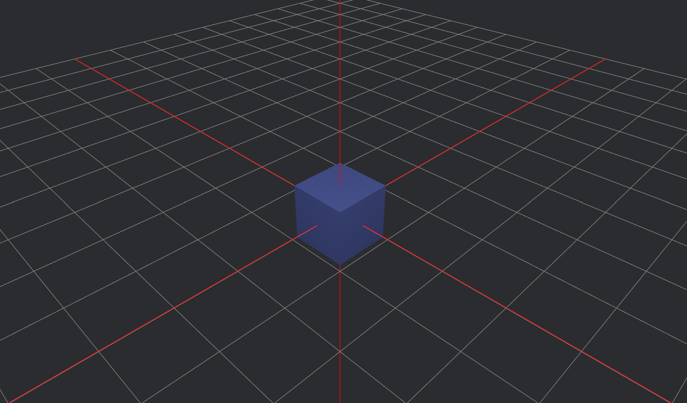
Notice that if you run our code, the scene will look something like this:

Which isn’t the best view of the cube and makes it look completely flat. Let’s add some lighting to fix this problem.
    // light
    commands.spawn((
        PointLight {
            shadows_enabled: true,
            ..default()
        },
        Transform::from_xyz(4.0, 8.0, 4.0) ));
The light is also an entity, so we spawn it in the setup() function and position it somewhere beside the camera.

Now the scene is well lit and the cube looks much better.
Visualizing the Axis
Since our scene is 3D and the camera is positioned at an angle, it can be difficult to visualize the axes. To make orientation easier, let’s draw a simple grid plane using gizmos, which will act as the floor of our scene. Let’s also add extra lines to clearly indicate where the X, Y, and Z axes are, helping us better understand the scene’s layout.
We will create a new function named grid(), which will draw the grid using gizmos.
fn grid(mut gizmos: Gizmos) {
    let grid_size = 10;
    let cell_size = 1.0;

    for i in -grid_size..=grid_size {
        let pos = i as f32 * cell_size;

        // Vertical grid lines
        gizmos.line(Vec3::new(pos, 0.0, -grid_size as f32), Vec3::new(pos, 0.0, grid_size as f32), GREY);

        // Horizontal grid lines
        gizmos.line(Vec3::new(-grid_size as f32, 0.0, pos), Vec3::new(grid_size as f32, 0.0, pos), GREY);
    }

    // Axis lines
    gizmos.line(Vec3::new(0.0, -10.0, 0.0), Vec3::new(0.0, 10.0, 0.0), RED); // Y-axis
    gizmos.line(Vec3::new(-10.0, 0.0, 0.0), Vec3::new(10.0, 0.0, 0.0), RED); // X-axis
    gizmos.line(Vec3::new(0.0, 0.0, -10.0), Vec3::new(0.0, 0.0, 10.0), RED); // Z-axis
}
Now we need to call the grid() function in main(). Make sure to run it in Update, so it executes every frame.
.add_systems(Update, grid)
Lets run our code and see what it looks like.
Much better
Enabling and Disabling the Grid
It would be useful if we could enable and disable the grid to get a better view of our object. To do this, we’ll spawn the grid as an entity with a component and write a simple if statement that checks if a key is pressed.
We’ll create a struct called Grid, which will contain a boolean field named enabled, which can be toggled when a key is pressed (let’s use the space key). It will also include other fields like grid size and cell size.
#[derive(Component)]
pub struct Grid {
    enabled: bool,
    size: i32,
    cell_size: f32,
}
Then, we spawn the grid entity with a Grid component in the setup() function.
// grid
commands.spawn(Grid {
    enabled: false,
    size: 10,
    cell_size: 1.0,
});
Now, we need to modify the grid() function to check if the space key is pressed.
fn grid(
    mut gizmos: Gizmos,
    keyboard_input: Res<ButtonInput<KeyCode>>,
    mut grid_query: Query<&mut Grid>,
) {
    for mut grid in &mut grid_query {
        if keyboard_input.just_pressed(KeyCode::Space) {
            grid.enabled = !grid.enabled;
        }

        if grid.enabled {
            for i in -grid.size..=grid.size {
                let pos = i as f32 * grid.cell_size;

                // Vertical grid lines
                gizmos.line(
                    Vec3::new(pos, 0.0, -grid.size as f32),
                    Vec3::new(pos, 0.0, grid.size as f32),
                    GREY,
                );

                // Horizontal grid lines
                gizmos.line(
                    Vec3::new(-grid.size as f32, 0.0, pos),
                    Vec3::new(grid.size as f32, 0.0, pos),
                    GREY,
                );
            }

            // Axis lines
            gizmos.line(Vec3::new(0.0, -100.0, 0.0), Vec3::new(0.0, 100.0, 0.0), RED);
            gizmos.line(Vec3::new(-100.0, 0.0, 0.0), Vec3::new(100.0, 0.0, 0.0), RED);
            gizmos.line(Vec3::new(0.0, 0.0, -100.0), Vec3::new(0.0, 0.0, 100.0), RED);
        }
    }
}
Since the grid is now an entity, we need to query it and access its Grid component before toggling its visibility.
I wrote grid.enabled = !grid.enabled; instead of grid.enabled == true;, because if I had used true, there wouldn’t be a way to turn the grid off. With this approach, we can toggle the grid on and off dynamically.
Now, you can run the code and try to press the space key to see if it works.
Object Movement
Let’s give our cube object some movement. Suppose it’s an item in a game that is hovering above the ground before the player picks it up. We can create this simple hovering illusion using the .sin() function.
Let’s create a new function called hover_cube():
fn hover_cube(mut transform: Single<&mut Transform, With<Mesh3d>>, time: Res<Time>) {
    let hover_speed = 3.0;
    let hover_height = 0.3;
    transform.translation.y = hover_height * (hover_speed * time.elapsed_secs()).sin();
}
The hover_cube() function makes the cube move up and down smoothly using a sine wave. The speed and height of the movement depend on the time elapsed, creating a floating effect.
Don’t forget to call the hover_cube() function in the main() function.
.add_systems(Update, hover_cube)
Also, adjust the cube’s position so it appears to hover above the plane, as it’s currently passing through it. We can fix this by setting a base height to keep it elevated.
fn hover_cube(mut transform: Single<&mut Transform, With<Mesh3d>>, time: Res<Time>) {
    let hover_speed = 3.0;
    let hover_height = 0.3;
    let base_height = 1.0; // Offset to keep the cube above the grid

    transform.translation.y = base_height + hover_height * (hover_speed * time.elapsed_secs()).sin();
}
Run the code and take a look—the cube should hover up and down above the plane.
Camera Movement
Now, let’s mess around with the camera’s position as well. We can make the camera spin around and orbit the cube.
First, let’s create an OrbitCamera component and add it to the camera entity. It will contain an angle, radius, and speed field.
#[derive(Component)]
struct OrbitCamera {
    angle: f32,
    radius: f32,
    speed: f32,
}
Don’t forget to edit the setup() function to make sure that the OrbitCamera component is also spawned with the camera entity.
// Camera with OrbitCamera component
commands.spawn((
    Name::new("Camera"),
    Camera3d::default(),
    Transform::from_xyz(5.0, 5.0, 5.0).looking_at(Vec3::ZERO, Vec3::Y),
    OrbitCamera {
        angle: 0.0,
        radius: 5.0,
        speed: 0.5,
    },
));
Now, let’s create an orbit_camera() function that calculates and updates the camera’s position, while ensuring it faces the cube.
fn orbit_camera(mut query: Query<(&mut Transform, &mut OrbitCamera)>, time: Res<Time>) {
    for (mut transform, mut orbit) in &mut query {
        orbit.angle += orbit.speed * time.delta_secs(); // Update angle

        let x = orbit.radius * orbit.angle.cos();
        let z = orbit.radius * orbit.angle.sin();
        transform.translation = Vec3::new(x, 3.0, z);
        transform.look_at(Vec3::ZERO, Vec3::Y);
    }
}
This function makes the camera orbit around the origin (which is where the cube is positioned) in a circular motion.
angle→ Represents the current rotation angle of the camera. This increases over time, causing the camera to move in a circular path.radius→ Defines the distance from the center of the orbit. A larger radius makes the camera move in a wider circle, while a smaller radius keeps it closer.speed→ Controls how fast the angle changes, affecting the speed of the orbiting motion. Higher values make the camera spin faster.
As angle updates each frame, cosine (cos) and sine (sin) functions calculate the new X and Z positions, ensuring smooth movement. The camera then looks at the center (Vec3::ZERO) to keep the target in focus.
Finally, run the code and see the results—the camera should be spinning around the cube, ensuring it’s visible from all sides.
You can also check out the finished code on my GitHub: spinny_cube
This is a very primitive example, but it gives an insight into Bevy’s 3D camera and objects. I will try to include more articles exploring the Bevy 3D world and 3D gameplay in general :)